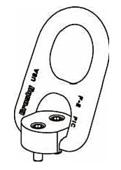


Pivot Hoist Ring HR-100 and HR-100M
HR-100 and HR-100M
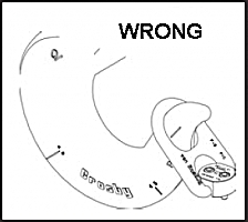
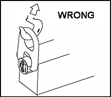
Pivot Hoist Ring Application / Assembly Instructions •Use pivot hoist ring only with ferrous metal (steel, iron) work piece. •After determining the loads on each pivot hoist ring select the proper size using the Working Load Limit (WLL) ratings in Table 1 for UNC threads or Table 2 for Metric threads (on next page). •Drill and tap the work piece to the correct size to a minimum depth of one-half the threaded bolt diameter plus the effective thread projection length (see Table 1 or Table 2, on next page). To select proper bolt and thread sizes (see Table 1 or Table 2, on next page). •Install the pivot hoist ring to recommended torque with a torque wrench making sure the pivot hoist ring body meets the load (work piece) surface. See rated load limit and bolt torque requirements imprinted on top of the pivot hoist ring body (see Table 1 or Table 2, on next page). •Never use spacers between the pivot hoist ring body and work piece surface. •Always select proper load rated lifting device for use with pivot hoist ring. •Attach lifting device ensuring free fit to pivot hoist ring bail (lifting ring) (Figure 1). •Apply partial load and check proper pivot. Ensure load alignment is in the direction of pivot (Figure 4). There should be no interference between load (work piece) and pivot hoist ring bail (Figure 2).
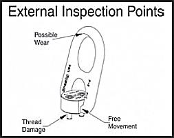
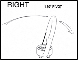
Pivot Hoist Ring Inspection / Maintenance •Always inspect pivot hoist ring before use. •Regularly inspect pivot hoist ring parts (Figure 3). •Never use pivot hoist ring that shows signs of corrosion, wear or damage. •Never use pivot hoist ring if bail is bent or elongated. •Do not use parts showing cracks, nicks or gouges. •Always be sure threads on bolts and receiving holes are clean, not damaged or worn, and fit properly. •Always check with torque wrench before using an already installed pivot hoist ring. •Always make sure there are no spacers (washers) used between pivot hoist ring body and the work piece surface. Remove any spacers (washers) and retorque before use. •Always ensure free movement of the bail. The bail should pivot 180 degrees (Figure 4). •Always be sure total work piece surface is in contact with the pivot hoist ring body mating surface. Drilled and tapped holes must be 90 degrees to load (work piece) surface. •Always make sure that the load is applied in the direction of pivot.
Operating Safety •Never exceed the capacity (WLL) of the pivot hoist ring, See Table 1 for UNC threads or Table 2 for Metric threads. •When using lifting slings of two or more legs, make sure the forces in the legs are calculated using the angle from the horizontal sling angle to the leg and select the proper size pivot hoist ring. When using a multi-leg lifting sling, the pivot hoist ring must be mounted so that the pivot direction is inline with the load applied.
* Ultimate load is 5 times the working load limit. Individually proof tested to 2-1/2 +Tightening torque values shown are based upon threads being clean, dry and ** Designed to be used with ferrous work piece only. ++Only use Crosby high strength replacement bolts. Do not use any other bolts.
|
|||||||||||||||||||||||||||||||||||||||||||||||||||||||||||||||||||||||||||||||||||||||||||