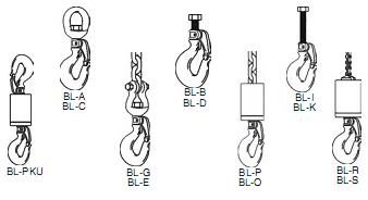
Crosby/Bullard Golden Gate Hooks
QUIC-CHECK® Hoist Hooks incorporate markings forged into the product which address two (2) QUIC-CHECK® features: Deformation Indicators - Two
strategically placed marks, one just below the shank or eye and the other on the® hook tip, which allows for a QUIC-CHECK® measurement to determine if the throat opening has changed, thus indicating abuse or overload.
To check, use a measuring device (i.e., tape measure) to measure the distance between the marks. The marks should align to either an inch or half-inch increment on the measuring device. If the measurement does not meet criteria, the hook should be inspected further for possible damage.
Angle Indicators - Indicates the maximum included angle which is allowed between two (2) sling legs in the hook. These indicators also provide the opportunity to approximate other included angles between two sling legs.
Important Safety Information Read and Follow
A visual periodic inspection for cracks, nicks, wear, gouges and deformation as part of a comprehensive documented inspection program, should be conducted by trained personnel in compliance with the schedule in ANSI B 30. 10.
For hooks used in frequent load cycles or pulsating loads, the hook and threads should be periodically inspected by Magnetic Particle or Dye Penetrant. (Note: Some disassembly may be required.)
See WARNING box and Figure 6 (on page 119) for special instructions for securing the nut to the shank at assembly.
Never use a hook whose throat opening has been increased, or whose tip has been bent more than 10 degrees out of plane from the hook body, or is in any other way distorted or bent. Note: A gate will not work properly on a hook with a bent or worn tip.
Manual - closing gates must be completely closed for the lock to work.
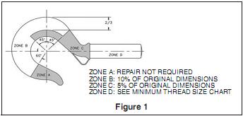
Never use a hook that is worn beyond the limits shown in Figure 1.
Remove from service any hook with a crack, nick, or gouge. Hooks with a nick or gouge shall be repaired by grinding lengthwise, following the contour of the hook, provided that the reduced dimension is within the limits shown in Figure 1 Contact Crosby Engineering to evaluate any crack.
Never repair, alter, rework, or reshape a hook by welding, heating, burning, or bending.
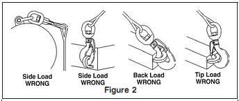
Never side load, back load, or tip load a hook. Side loading, back loading and tip loading are conditions that damage and reduce the capacity of the hook. (See Figure 2).
• Eye hooks, shank hooks and swivel hooks are designed to be used with wire rope or chain. Efficiency of assembly may be reduced when used with synthetic material.
WARNING |
•Loads may disengage from hook if proper procedures are not followed.
•A falling load may cause serious injury or death.
•Before using, inspect the hook and gate daily to ensure it is in proper operating condition.
•Failure to properly insert the pin could result in the load falling.
•All Golden Gate® Hooks with threaded shanks require a pin to secure the nut to the shank. This pin prevents the nut from backing off or unscrewing from the threads and causing the load to drop.
•If the pin and nut are removed from the shank to replace any hook components, the pin and nut must be installed before use.
NOTE: 1. If a solid pin was used, the old pin "must"be discarded and a new pin inserted to secure the nut to the shank. 2. If a spring pin (coil type) was used, it may be reused provided that the spring pin and / or the drill hole was not damaged.
•The gate is not a load-bearing device. Do not allow the sling or other loads to bear against the gate.
•Threads may corrode and / or strip and drop the load.
•Hands, fingers and body should be kept away from the hook and load whenever possible.
•Never apply more force than the hook's assigned Working Load Limit (WLL) rating.
•Read and understand these instructions before using. |
 |
 |
- The use of a latch may be mandatory by regulations or safety codes: e.g., OSHA, MSHA, ANSI/ASME B30, Insurance etc.
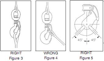
- Always make sure the hook supports the load (See Figure 3). The gate must never support the load (See Figure 4).
- When placing two (2) sling legs in hook, make sure the angle from the vertical to the outermost leg is not greater than 45 degrees, and the included angel between the legs does not exceed 90 degrees* (See Figure 5).
- See ANSI/ASME B30.10 "Hooks" for additional information.
- If any of the following conditions exist, remove hook from service immediately and repair with genuine Crosby / Bullard Golden Gate® hook parts or replace the hook.
- The gate does not lock in the closed position.
- The gate is worn, deformed, inoperative, or fails to bridge the hook throat opening.
- Load pins or bolts in the chain connectors are worn or bent.
- When hook is used to support a hoist, the weight of the hoist must be deducted from the assigned hook Working Load Limit.
- The rated capacity of chain connector hook assemblies must equal or exceed the capacity of the hoist.
* For two legged slings with angles greater than 90°, use an intermediate link such as a master link or bolt type shackle to collect the legs of the slings. The intermediate link can then be placed over the hook to provide an in-line load on the hook. This approach must also be used when using slings with three or more legs.
Important - Basic Machining and Thread Information Read and Follow
 |
- Wrong thread and/or shank size can cause stripping and loss of load.
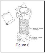
- The maximum diameter is the largest diameter that will fit into the gate.
- All threads must be Class 2 or better.
- The minimum thread length engaged in the nut should not be less than one (1) thread diameter.
- All nuts must be secured to the shank by cross drilling the nut and threaded shank and inserting the appropriate coil type spring pin (See WARNING box and Figure 6 for special instructions).
- Coil type spring pin must be as long as the distance across the nut flats or diameter (See Figure 6).
- Consult the Crosby / Bullard Golden Gate® Hook Identification and Working Load Limit Chart (See below) for the coil type spring pin diameter.
- Remove any hook from service that requires a larger coil type spring than that shown in the chart below.
- Hook shanks are not intended to be swaged on wire rope or rod.
- Hook shanks are not intended to be drilled and internally threaded.
- Crosby cannot assume responsibility for, (A) the quality of machining, (B) the type of application, or (C) the means of attachment to the power source or load.
•Consult the Crosby/Bullard Golden Gate® Hook Identification & Working Load Limit Chart (below) for the minimum thread size for assigned Working Load Limits (WLL). +
•Remove from service any hook which has threads corroded more than 20% of the nut engaged length.
| Hook / Gate Size |
Working Load Limit** + (tons) |
Maximum Shank Dimeter (in.) |
Maximum Thread Size |
Spring* Pin Size (in.) |
Drilled Hole Size (in.) |
Hook / Gate Size |
Working Load Limit (tons) |
Maximum Shank Dimeter (in.) |
Maximum Thread Size |
Spring* Pin Size (in.) |
Drilled Hole Size (in.) |
| 1 |
.5 |
- |
- |
- |
- |
11 |
9.2 |
1.497 |
1-1/2 - 6unc |
5/16 |
.308/.319 |
| 2 |
1.0 |
.498 |
1/2 - 13 unc |
1/8 |
.124/.129 |
12 |
12.3 |
1.622 |
1-5/8 - 5-1/2unc |
5/16 |
.308/.319 |
| 3 |
1.4 |
.559 |
9/16 - 12 unc |
1/8 |
.124/.129 |
13 |
15.0 |
1.747 |
1-3/4 - 5 unc |
3/8 |
.370/.383 |
| 4 |
1.7 |
.623 |
5/8 - 11 unc |
1/8 |
.124/.129 |
14 |
18.5 |
1.997 |
2 - 4-1/2 unc |
3/8 |
.370/.383 |
| 5 |
2.3 |
.747 |
3/4 - 10 unc |
5/32 |
.155/.160 |
16 |
24.7 |
2.747 |
2-3/4 - 4unc |
1/2 |
.493/.510 |
| 6 |
4.0 |
.872 |
7/8 - 9 unc |
3/16 |
.185/.192 |
16-A |
33.0 |
2.747 |
2-3/4 - 4unc |
1/2 |
.493/.510 |
| 7 |
4.2 |
.997 |
1 - 8 unc |
3/16 |
.185/.192 |
17 |
49.5 |
3.996 |
4 - 4unc |
3/4 |
.743/.760 |
| 8 |
5.5 |
1.112 |
1-1/8 - 7 unc |
1/4 |
.247/.256 |
17-A |
66.0 |
3.996 |
4 - 4unc |
3/4 |
.743/.760 |
| 9 |
7.2 |
1.247 |
1-1/4 - 7 unc |
1/4 |
.247/.256 |
- |
- |
- |
- |
- |
- |
*Heavy Duty Coil Spring Pin.
**Minimum ultimate strength is 4 times the Working Load Limit.
+ Working Load Limit - The maximum mass of force which the product is authorized to support in general service when the pass is applied in-line, unless note otherwise with respect to centerline of the product. This term is used intachangeably with the following terms: 1. WLL, 2. Rate Load Value, 3. Safe Working Load, 5. Resultant Safe Working Load. Ultimate Load is 4 times the Working Load.
|