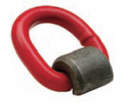


Weld-on Pivoting Link S-265
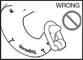
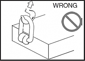
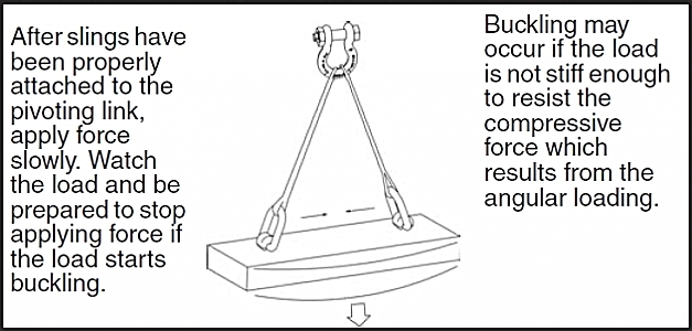
Important Safety Information -Read and Follow •Use weld-on pivoting link only with ferrous metal (steel) work piece. •After determining the loads on each weld-on pivoting link, select the proper size using the Working Load Limit (WLL) ratings in Table 1 on next page. •Always make sure the weld-on pivoting link and mounting surface is free of dirt or contaminants before installation. •Never use spacers between the weld-on pivot link and mounting surface. •Always select proper load rated lifting device for use with weld-on pivoting link. •Attach lifting device ensuring free movement of weld-on pivoting link bail (Figure 1). •Apply partial load and check proper alignment. There should be no interference between load (work piece) and weld-on pivoting link (Figure 2). •Always ensure free movement of bail. The bail should pivot 180 degrees (Figure 4). •The support structure that the pivot link is attached to must be of suitable size, composition and quality to support the anticipated loads of all operating positions. The required support structure thickness for a given application is dependent on variables such as unsupported length and material strength, and should be determined by a qualified individual. •Never repair, alter, rework or reshape the pivoting link bail by welding, heating, burning or bending.
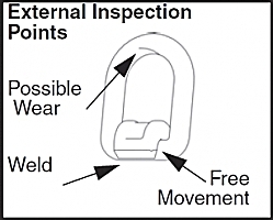
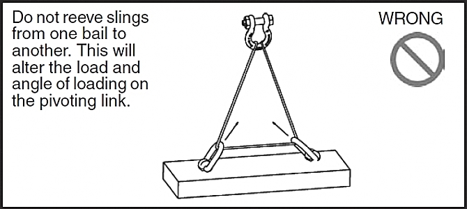
Weld-on Pivoting Link Inspection / Maintenance •Always inspect weld-on pivoting link before use. •Regularly inspect weld-on pivoting link parts (Figure 3). •Never use weld-on pivoting link that shows signs of corrosion, wear or damage. •Never use weld-on pivoting link if bail is bent or elongated. •Do not use part showing cracks, nicks or gouges. •Always make sure there are no spacers used between weld-on pivoting link and the mounting surface. •Always be sure work piece surface is in total contact with the weld-on pivoting link base mating surface. •Always inspect the weld-on pivoting link bail and base for wear. •A visual periodic inspection of the weld should be performed. Check the weld visually, or use a suitable NDE method if required. Operating Safety •Never exceed the capacity (WLL) of the weld-on pivoting link (Table 1, next page). •Never apply load except in line with the pivot direction (Figure 4). •When using lifting slings of two or more legs, make sure the forces in the legs are calculated using the angle from the horizontal sling angle to the leg and select the proper size link.
Weld-on Pivoting Link Welding Guidelines 1. Select the correct size weld-on pivoting link to be used. Be sure to calculate the maximum load that will be applied to the weld-on pivoting link. 2. Place the weld-on pivoting link onto the mounting surface. The bottom of the link base must be parallel and even with the mounting surface. 3. Welding is to be performed by a qualified welder using a qualified procedure in accordance with American Welding Society and/or American Society of Mechanical Engineers requirements. Alway follow your country or local mandatory regulations or codes. 4. The following welding recommendations should be included in the qualified procedure for welding to low or medium carbon plate steel. For welding to other grades of steel, a qualified weld procedure must be developed. A. Weld material is to have a minimum tensile strength of 70,000 PSI (such as AWS A5.1 E-7018). Observe the electrode manufacturer's recommendations. Completely fill internal fillet created between weld-on pivoting link base and mounting surface. B. Before welding, all weld surfaces must be clean and free from rust, grease, paint, slag and any other contaminants. C. Fillet weld leg size should be minimum shown in Table 1. Weld profiles to be in accordance with AWS. Weld size is measured by length of leg. D. Welding should be carried out in a minimum of two passes to ensure adequate root penetration at the base of the pivoting link. E. Weld full length of "D" dimension on both sides of link base (Figure 5). F. Do not weld close to the bail. After welding, ensure bail pivots full 180° without interfering with the weld. G. Do not rapidly cool the weld. H. The ends of the weld must be ground sufficiently so that the weld-on pivoting link will fit flush against the mounting surface. I. A thorough inspection of the weld should be performed. No cracks, pitting, inclusions, notches or undercuts are allowed. If doubt exists, use a suitable NDE method, such as magnetic particle or liquid penetrant to verify. J. If repair is required, grind out the defect and re-weld using the original qualified procedure.
** Designed to be used with ferrous work piece only.
|
||||||||||||||||||||||||||||||||||||||||||||||||||||||||||||||||||||||||||||||||||||||||||||||||||||||||||||