


Weld-on Hooks BH-313Important Safety Information -Read and Follow
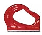
BH-313
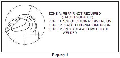
Important Safety Information -Read and Follow •Weld-On hooks are to only be welded to a structure, equipment or machinery in an area (load point) approved by the original equipment manufacturer. (Some manufacturers may not approve the modification of their product.) •For hydraulic excavator lift capacity rating, refer to SAE standard J1097. •A visual periodic inspection for cracks, nicks, wear, gouges and deformation as part of a comprehensive documented inspection program, should be conducted by trained personnel. •A visual periodic inspection of the weld should be performed. Check the weld visually, or use a suitable NDE method if required. •As excavator buckets are not specifically designed for constant use with excavator hooks, we recommend regular and very thorough inspection of the excavator bucket welding area to insure no distortion has been made to the work area. •Never use a hook whose throat opening has been increased, or whose tip has been bent more than 10 degrees out of plane from the hook body, or is in any other way distorted or bent. Note: A latch will not work properly on a hook with a bent or worn tip. •Never use a hook that is worn beyond the limits shown in Figure 1. •Remove from service any hook with a crack, nick, or gouge. Hooks with a nick or gouge shall be repaired by grinding lengthwise, following the contour of the hook, provided that the reduced dimension is within the limits shown in Figure 1. Contact Crosby Engineering to evaluate any crack.
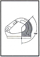
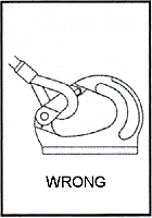
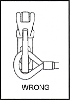
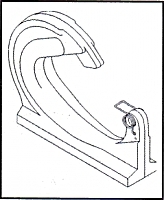
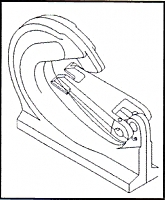
•Never repair, alter, rework, or reshape a hook by welding, heating, burning, or bending. •Always make sure the hook supports the load. The load is to be applied within the range shown in Figure 2. The latch must never support the load (See Figure 3).
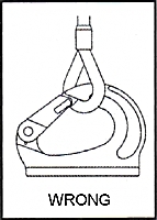
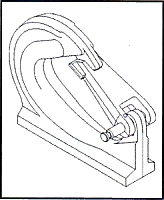
•Never side load (See Figure 4), or tip load (See Figure 5) a hook.
•The use of a latch may be mandatory by regulations or safety codes; e.g., OSHA, MSHA, ANSI/ASME B30, Insurance, etc. (Note: When using latches, see instructions in "Understanding: The Crosby Group Warnings" for further information.) •Ensure latch functions properly. Use only genuine Crosby replacement parts. •Never attach more than one sling directly in hook. For collecting two or more slings to the hook, use proper hardware. •See ANSI/ASME B30.10 "Hooks" for additional information.
•The strength of the weld-on hook depends upon the method of attachment. Extreme care must be used in process. •The support structure that the hook is attached to must be of suitable size, composition and quality to support the anticipated loads of all operating positions. The required support structure material thickness for a given application is dependent on variables such as unsupported length and material strength, and should be determined by a qualified individual. Minimum plate thickness required to support the welds are shown in Table 1.
•Position the hook to insure that the load is applied in the plane of the hook, and the load is supported by the hook in all operating positions. Insure that the hook does not interfere with the operation of other mechanisms or cause pinch points. •Insure that the maximum gap between hook base and support does not exceed 1/8". Modify the support structure if required to reduce gap. •When welding hook to carbon or low alloy steels (less than .40% carbon), the following welding recommendations are to be followed. For welding hook to other grades of steel, a qualified weld procedure must be developed. Crosby hook material is AISI 8622 modified. •Welding is to be performed by a qualified welder using qualified procedure in accordance with American Welding Society (AWS), and/or American Society of Mechanical Engineers (ASME) requirements. •Welding electrode to be in accordance with AWS A5.4 E-312-16. Observe the electrode manufacturers recommendations. •Welding preheat range outlined below. -Minimum preheat temperature: 212F (100C) -Maximum temperature: 716F (380C)
•Before welding, the surface to be welded on, including the hook and support structure, must be clean and free from rust, grease and paint. •Fillet weld leg size should be of minimum shown in Table 1. Weld profiles to be in accordance with AWS. Weld size is measured by length of leg. •Welding should be carried out completely around base in a minimum of two passes to insure adequate root penetration at the base of the hook. •Do not rapidly cool the weld. •After welding, a visual inspection of the weld should be performed prior to painting. •No Cracks, pitting, inclusions, notches or undercuts are allowed. if doubt exists, use a suitable NDE method, such as Magnetic particle or Liquid Penetrate to verify. •If repair is required on weld, grind out defect and re-weld using original qualified procedure. •After welding, the assembly should be proof tested before putting into service.
Important - Instructions for Assembling S-4313 Latch on BH-313 Weld-On Hook
|
|||||||||||||||||||||||||||||||||||||||||||||||||||||||||||||||||||||