


Tackle Block and Sheeve AssemblyTackle Block and Sheave Assembly Warning, Use & Maintenance Information
Important: For maximum safety and efficiency, tackle block and sheave systems must be properly designed, used, and maintained. You must understand the use of tackle block components and sheaves in the system. These instructions provide this knowledge. Read them carefully and completely. Some parts of these instructions must use technical words and detailed explanations. NOTE: If you do not understand all words, diagrams, and definitions - DO NOT TRY TO DESIGN OR USE A TACKLE BLOCK OR SHEAVE SYSTEM! For further assistance, call: In U.S.A. - Crosby Engineered Products Group at 800-777-1555. In CANADA - Crosby Canada (905) 451-9261. IN EUROPE - N.V. Crosby Europe 32-15-757125. As you read instructions, pay particular attention to safety information in bold print.
KEEP INSTRUCTIONS FOR FUTURE USE - DO NOT THROW AWAY! General Cautions or Warnings Ratings shown in Crosby Group literature are applicable only to new or "in as new" products. Working Load Limit ratings indicate the greatest force or load a product can carry under usual environmental conditions. Shock loading and extraordinary conditions must be taken into account when selecting products for use in tackle block systems. Working Load Limit ratings are based on all sheaves of tackle block system being utilized. If all sheaves are not utilized, balance must be maintained, and the Working Load Limit must be reduced proportionally to prevent overloading sheave components. Changes from full sheave reeving arrangement should be only at the recommendation of a qualified person, and incorporate good rigging practices. In general, the products displayed in Crosby Group literature are used as parts of a system being employed to accomplish a task. Therefore, we can only recommend within the Working Load Limits, or other stated limitations, the use of products for this purpose. The Working Load Limit or Design (Safety) Factor of each Crosby product may be affected by wear, misuse, overloading, corrosion, deformation, intentional alteration, and other use conditions. Regular inspection must be conducted to determine whether use can be continued at the catalog assigned WLL, a reduced WLL, a reduced Design (Safety) Factor, or withdrawn from service. Crosby Group products generally are intended for tension or pull. Side loading must be avoided, as it exerts additional force or loading which the product is not designed to accommodate. Always make sure the hook supports the load. The latch must never support the load. Welding of load supporting parts or products can be hazardous. Knowledge of materials, heat treatment, and welding procedures are necessary for proper welding. Crosby Group should be consulted for information. Crane component parts, i.e. the boom, block, overhaul ball, swivel, and wire ropes are metallic and will conduct electricity. Read and understand OSHA standard covering crane and derrick operations (29 CFR 1926.550 SUBPART N) before operating proximate to power lines.
Definitions STATIC LOAD - The load resulting from a constantly applied force or load. WORKING LOAD LIMIT - The maximum mass or force which the product is authorized to support in general service when the pull is applied in-line, unless noted otherwise, with respect to the center line of the product. This term is used interchangeably with the following terms.
WORKING LOAD - The maximum mass or force which the product is authorized to support in a particular service. PROOF LOAD - The average force applied in the performance of a proof test; the average force to which a product may be subjected before deformation occurs. PROOF TEST - A test applied to a product solely to determine non conforming material or manufacturing defects. ULTIMATE LOAD - The average load or force at which the product fails, or no longer supports the load. SHOCK LOAD - A force that results from the rapid application of a force (such as impacting and/or jerking) or rapid movement of a static load. A shock load significantly adds to the static load. DESIGN (SAFETY) FACTOR - An industry term denoting a product's theoretical reserve capability; usually computed by dividing the catalog Ultimate Load by the Working Load Limit. Generally expressed for blocks as a ratio of 4 to 1. TACKLE BLOCK - An assembly consisting of a sheave(s), side plates, and generally an end fitting (hook, shackle, etc.) that is used for lifting, lowering, or applying tension. SHEAVE / SHEAVE BEARING ASSEMBLY - Purchased by O.E.M. or end user to be used in their block or lifting system design.
Fitting Maintenance Fittings, including hooks, overhaul balls, shackles, links, etc., may become worn and disfigured with use, corrosion, and abuse resulting in nicks, gouges, worn threads and bearings, sharp corners which may produce additional stress conditions and reduce system load capacity. Grinding is the recommended procedure to restore smooth surfaces. The maximum allowance for reduction of a product's original dimension due to wear or repair before removal from service is:
Any crack or deformation in a fitting is sufficient cause to withdraw the product from service.
Selection Guide Some of the blocks shown in Crosby Group literature are named for their intended use and selection is routine. A few examples include the "Double Rig Trawl Block" used in the fishing industry, the "Well Loggers Block" used in the oil drilling industry, and the "Cargo Hoisting Block" used in the freighter boat industry and "Derrick and Tower Block" used for hoisting personnel. Others are more generally classified and have a variety of uses. They include snatch blocks, regular wood blocks, standard steel blocks, etc. For example, snatch blocks allow the line to be attached by opening up the block instead of threading the line through the block. This feature eliminates the use of rope guards and allows various line entrance and exit angles to change direction of the load. These angles determine the load on the block and/or the block fitting.(See "Loads on Blocks" on page 345.) Snatch blocks are intended for infrequent and intermittent use with slow line speeds. A tackle block sheave assembly is one element of a system used to lift, change direction or drag a load. There are other elements in the system including the prime mover (hoist, winch, hand), supporting structure, power available, etc. All of these elements can influence the type of tackle block or sheave required. When selecting a block or sheave for the system in your specific application, you should consider the other elements as well as the features of the blocks and sheaves shown in Crosby Group literature. To select a tackle block or sheave to fit your requirements, consider the following points:
Common (Plain) Bore for very slow line speeds and very infrequent use (high bearing friction). Self Lubricating Bronze Bushings for slow line speeds and infrequent use (moderate bearing friction). Bronze Bushing with pressure lubrication for slow line speeds and more frequent use at greater loads (moderate bearing friction). Anti-friction Bearings for faster line speeds and more frequent use at greater loads (minimum bearing friction).
10. How will the block or sheave be maintained? Do conditions in your application require special maintenance considerations? (See "Tackle Block and Sheave Maintenance," page 344 and "Fitting Maintenance," page 343.) 11. Reference current edition of "Wire Rope Users Manual" for additional sheave design and maintenance information. Tackle Block and Sheave Maintenance Tackle Blocks and Sheaves must be regularly inspected, lubricated, and maintained for peak efficiency and extended usefulness. Their proper use and maintenance is equal in importance to other mechanical equipment. The frequency of inspection and lubrication is dependent upon frequency and periods of use, environmental conditions, and the user's good judgment. Inspection: As a minimum, the following points should be considered:
Lubrication: The frequency of lubrication depends upon frequency and period of product use as well as environmental conditions, which are contingent upon the user's good judgment. Assuming normal product use, the following schedule is suggested when using lithium-base grease of a medium consistency. Sheave Bearings Tapered Roller Bearings - Every 40 hours of continuous operation or every 30 days of intermittent operation. Roller Bearings - Every 24 hours of continuous operation or every 14 days of intermittent operation. Bronze Bushings - (Not Self Lubricated) - Every 8 hours of continuous operation or every 14 days of intermittent operation. Self Lubricating Bronze Bushing - are for slow line speeds and infrequent use (moderate bearing friction). Frequent inspection is required to determine the condition of bushing. Hook Bearings Anti Friction - Every 14 days for frequent swiveling; every 45 days for infrequent swiveling. Bronze Thrust Bushing or No Bearing - Every 16 hours for frequent swiveling; every 21 days for infrequent swivel-ing. Tackle Block Maintenance also depends upon proper block selection (see "Loads on Blocks"), proper reeving (see "The Reeving of Tackle Blocks"), consideration of shock loads, side loading, and other adverse conditions. Sheave Bearing Application Information Sheaves in a system of blocks rotate at different rates of speed, and have different loads. When raising and lowering, the line tension is not equal throughout the system. Refer to Page 328 "How to Figure Line Parts" for assistance in determining lead line loads used for bushing or bearing selection. BRONZE BUSHINGS Bronze Bushings are used primarily for sheave applications using slow line speed, moderate load, and moderate use. The performance capability of a bearing is related to the bearing pressure and the bearing surface velocity by a relationship known as true PV (Maximum Pressure - Velocity Factor). The material properties of the Bronze Bushings furnished as standard in Crosby catalog sheaves are: (BP) Maximum Bearing Pressure : 4500 PSI (BV) Maximum Velocity at Bearing :1200 FPM (PV) Maximum Pressure Velocity Factor: 55000 (It should be noted that due to material property relations, the maximum BP times the maximum BV is NOT equal to the maximum PV.)
Formula for Calculating Bearing Pressure:
BP = Line Pull x Angle Factor / Shaft Size x Hub Width
Note: Angle Factor Multipliers listed on page 345.
Formula for Calculating Bearing Velocity: BV = PV / BP
Formula for Calculating Line Speed:
Line Speed = BV (Tread Diameter + Rope Diameter) / Shaft Diameter
Calculations can be made to find the maximum allowable line speed for a given total sheave load. If the required line speed is greater than the maximum allowable line speed calculated, then increase the shaft size and/or the hub width and recalculate. Continue the process until the maximum allowable line speed is equal to or exceeds the required line speed.
Example Using a 14 in. sheave (Stock # 917191; refer to wire rope sheave section of General Catalog for dimensions) with a 4,600 lbs. line pull and an 80° angle between lines determine maximum allowable line speed. BP = (4,600 lbs. x 1.53) * (1.50 x 1.62) = 2,896 PSI (line pull) (angle factor) \ (Hub Width) (Shaft Size) BV = 55,000 * 2,896 = 19 FPM Allowable (PV Factor) (BP)
Line Speed = 19 x (12 + .75) * 1.50 = 161.5 FPM ALLOWABLE (BV) (Tread Dia. + Rope Size) h (Shaft Dia.) If the application required a line speed equal to 200 FPM, then another calculation would be necessary. Trying another 14 in. sheave (stock # 4104828) under the same loading conditions, the results are as follows:
BP = (4,600 lbs. x 1.53) / (2.75 x 2.31) = 1,108 PSI BV = 55,000 / 1,108 = 50 FPM Line Speed = 50 x (12.25 + .75) / 2.75 = 236 FPM ALLOWABLE
COMMON (PLAIN) BORE Very slow line speed, very infrequent use, low load. ROLLER BEARING Faster line speeds, more frequent use, greater load. Refer to manufacturer's rating. Reference appropriate bearing manufacturer's catalog for proper bearing selection procedure.
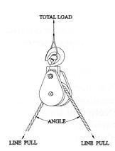
Loads on Blocks The Working Load Limit (WLL) for Crosby Group blocks indicates the maximum load that should be exerted on the block and its connecting fitting. This total load value may be different from the weight being lifted or pulled by a hoisting or hauling system. It is necessary to determine the total load being imposed on each block in the system to properly determine the rated capacity block to be used. A single sheave block used to change load line direction can be subjected to total loads greatly different from the weight being lifted or pulled. The total load value varies with the angle between the incoming and departing lines to the block. The following chart indicates the factor to be multiplied by the line pull to obtain the total load on the block.
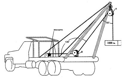
Example A (Calculations for determining total load value on single line system.) A gin pole truck lifting 1,000 lbs.
There is no mechanical advantage to a single part load line system, so winch line pull is equal to 1,000 lbs. or the weight being lifted. To determine total load on snatch block A: A = 1,000 lbs. x 1.81 = 1,810 lbs. (line pull)(factor 50° angle)
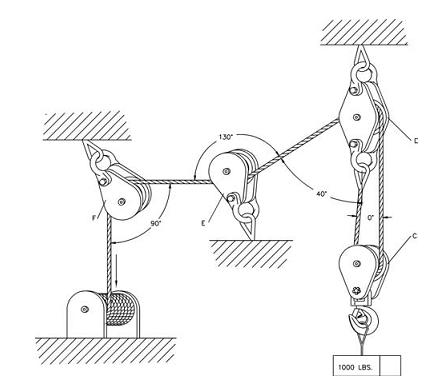
To determine total load on toggle block B: B = 1,000 lbs. x .76 = 760 lbs. (line pull) (factor 135° angle) Example B (Calculation for determining total load value for mechanical advantage system.) Hoisting system lifting 1,000 lb. using a traveling block. The mechanical advantage of traveling block C is 2.00 because two (2) parts of load line support the 1,000 lb. weight. (Note that this example is simplified for determination of resultant load on blocks. Lead line pull will be greater than shown due to efficiency losses.) (To determine single line pull for various bearing efficiency see "How to Figure Line Parts" page 348.)
To Determine Line Pull: Line Pull = 1,000 lbs. -r 2.00 = 500 lbs.
To determine total load on traveling block C: C = 500 lbs. x 2.0 = 1,000 lbs. (line pull)(Factor 0° angle) To determine total load on stationary block D: D= 500 lbs. x 1.87 + 500 lbs. = 1,435 lbs. (line pull) ^ (dead-end load) (Factor 40° angle)
To determine total load on block E: E = 500 lbs. x .84 = 420 lbs. (line pull) (Factor 130° angle) To determine total load on block F: F = 500 lbs. x 1.41 = 705 lbs. (line pull) (Factor 90° angle)
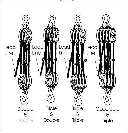
The Reeving of Tackle Blocks In reeving of tackle blocks, there are many methods. The method discussed below is referred to as "Right Angle" reeving. Please consult your rigging manual for other methods of reeving. RIGHT ANGLE REEVING In reeving a pair of tackle blocks, one of which has more than two sheaves, the hoisting rope should lead from one of the center sheaves of the upper block to prevent toppling and avoid injury to the rope. The two blocks should be placed so that the sheaves in the upper block are at right angles to those in the lower one, as shown in the following illustrations. Start reeving with the becket or dead end of the rope. Use a shackle block as the upper one of a pair and a hook block as the lower one as seen below. Sheaves in a set of blocks revolve at different rates of speed. Those nearest the lead line revolve at the highest rate of speed and wear out more rapidly. All sheaves should be kept well lubricated when in operation to reduce friction and wear. Reeving Diagram
Sheave Size & Wire Rope Strength Strength Efficiency Bending wire rope reduces its strength. To account for the effect of bend radius on wire rope strength when selecting a sheave, use the table below: Fatigue Life Repeated bending and straightening of wire rope causes a cyclic change of stress called "fatiguing." Bend radius affects wire rope fatigue life. A comparison of the relative effect of sheave diameter on wire rope fatigue life can be determined as shown below:
Ratio A = Sheave Diameter / Rope Diameter Example To determine the strength efficiency of 1/2" diameter wire rope using a 10" diameter sheave: Ratio A = 10" (sheave diameter) / 1/2 (wire rope diameter) = 20 Refer to ratio A of 20 in the table then check the column under the heading "Strength Efficiency Compared to Catalog Strength in %"...91% strength efficiency as compared to the catalog strength of wire rope.
Ratio B - Sheave Diameter / Rope Diameter Relative Fatigue Bending Life = Relative Fatigue Bending Life Sheave #1 / Bending Life Relative Fatigue Bending Life (Sheave #2)
Example To determine the extension of fatigue life for a 3/4" wire rope using a 22.5" diameter sheave versus a 12" diameter sheave: Ratio B = 22.5" (sheave diameter) / 3/4" (wire rope diameter) = 30
Ratio B = 12 (sheave diameter) / 3/4" (wire rope diameter) = 16 The relative fatigue bending life for a ratio B of 16 is 2.1 (see above Table) and ratio B of 30 is 10. Therefore, we expect extension of fatigue life using a 22.5" diameter sheave to be 4.7 times greater than that of a 12" diameter sheave.
How to Determine Overhauling Weights To determine the weight of the block or overhaul ball that is required to free fall the block, the following information is needed: size of wire rope, number of line parts, type of sheave bearing, length of crane boom, and drum friction (use 50 pounds, unless other information is available).
The Formula is:
Required Block Weight = [(Boom Length x Factor A) + Drum Friction] x Factor B
Example: To determine the required block or overhaul weight using 5 parts of 7/8" diameter wire rope, a 50 ft. boom and roller bearing sheaves: Required Block = [(50 ft x 1.42)+ 50 lbs.] x 5.38 = 651lbs. Weight (Boom length)\^ (Drum Friction) \^ (Factor A) (Factor B) How to Figure Line Parts Sheaves in a system of blocks rotate at different rates of speed, and have different loads. When raising and lowering, the line tension is not equal throughout the system. To help figure the number of parts of line to be used for a given load, or the line pull required for a given load, (for example, use Reeving Diagram on page 346. Only numbered lines shall be used in the calculation). The following ratio table is provided with examples of how to use it. The ratios are applicable for blocks as shown on page 346 and also independent sheave systems that line is reeved through.
Ratio A or B = Total Load to be Lifted / Single Line Pull (lbs.)
After calculating Ratio A or B, consult table to determine number of parts of line. Examples: To find the number of parts of line needed when weight of load and single line pull are known, and using Bronze Bushed Sheaves.
Ratio A = 72,180 lbs. (load to be lifted) / 8,000 lbs (single line pull) = 9.02 (Ratio A)
In table above refer to ratio 9.02 or next highest number, then check column under heading "Number of Line Parts" = 12 parts of line to be used for this load. To find the single line pull needed when weight of load and number of parts of line are known, and using Anti-Friction Bearing Sheaves. Single Line Pull= 68,000 lbs.(load to be lifted) / 7.32 (Ratio B of 8 part line) = 9,290lbs. 9,290 lbs. single line pull required to lift this load on 8 parts of line. To find the lift capacity when the parts of line and single line pull are known, and using anti-friction bearing sheaves. 10,000 lbs. (Single line pull) _______________________________ = 47,100 lbs. (Lift Capacity) 10,000 lbs. single line pull with 5 parts of line will accommodate 47,100 lbs. lift capacity.
Repairs For repair of blocks, contact the following numbers for return material authorization. IN U.S.A. - Crosby Engineered Products Group at (800) 777-1555 IN CANADA - Crosby Canada at (905)451-9261 IN EUROPE - N.V. Crosby Europe at 32 15 757125
Your block, after receipt by Crosby, will be inspected and a free estimate of repair charges will be provided. Authorization for repairs from block owners must be given to Crosby before repairs are made. Transportation charges, both to and from factory, are to be paid by the block owner.
Additional Information For information concerning parts, special application, or situations requiring other features, contact:
U.S.A. The Crosby Group, Inc. P.O. Box 3128 Tulsa, OK 74101-3128 (918) 834-4611 FAX (918) 832-0940 www.thecrosbygroup.com crosbygroup@thecrosbygroup.com
CANADA Crosby Canada 145 Heart Lake Road Brampton, Ontario, Canada L6W 3K3 (905) 451-9261 FAX (877)260-5106
EUROPE Industriepark Zone B nr 26 B-2220 Heist-op-den-Berg. Belgium 32-15-75-71-25 FAX 32-15-75-37-64 www.thecrosbygroup.com sales@crosbyeu.com
How to Find Your Nearest Crosby Distributor To locate your nearest Crosby Distributor, call: IN U.S.A. - Crosby Customer Service Department at (800) 772-1500 IN CANADA - Crosby Canada at (905) 451-9261 IN EUROPE - N.V. Crosby Europe at 32 15 757125
|
||||||||||||||||||||||||||||||||||||||||||||||||||||||||||||||||||||||||||||||||||||||||||||||||||||||||||||||||||||||||||||||||||||||||||||||||||||||||||||||||||||||||||||||||||||||||||||||||||||||||||||||||||||||||||||||