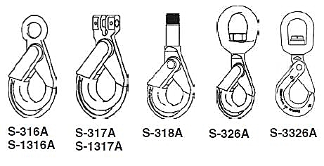
Shur-Loc Hooks
WARNING AND APPLICATION INSTRUCTIONS
 |
WARNING |
- Loads may disengage from hook if proper procedures are not followed.
- A falling load may cause serious injury or death.
- Positive locking latch will unlock when trigger is depressed. Never use hook unless hook and latch are fully closed and locked.
- Keep body parts clear of pinch point between hook tip and hook latch when closing.
- Keep hand(s) from between throat of hook and sling or other device.
- Do not use hook tip for lifting.
- Shank threads may corrode and/or strip and drop the load.
- Remove securement nut to inspect threads for corrosion or to replace S-326A bearing washers (2) and or S-3326 thrust bearing.
- Never apply more force than the hook's assigned Working Load Limit (WLL) rating.
- See OSHA Rule 1926.550 (g) for personnel hoisting by cranes or derricks. A Crosby 316A, 317A, 318A, 326A, 3326, 1316A, or 1317A hook may be used for lifting personnel.
- Use only genuine Crosby parts as replacements.
- Read and understand these instructions before using hook.
|
Important Safety Information -Read and Follow
- A visual periodic inspection for cracks, nicks, wear, gouges and deformation as part of a comprehensive documented inspection program, should be conducted by trained personnel in compliance with the schedule in ANSI B30.10.
- For hooks used in frequent load cycles, pulsating loads, or severe duty as defined by ASME B30.10, the hook and threads should be periodically inspected by Magnetic Particle or Dye Penetrant. (Note: Some disassembly may be required.)
- Never use a hook whose throat opening has been increased 5%, not to exceed 1/4", or shows any visible apparent bend or twist from the plane of the unbent hook, or is in any other way distorted or bent. NOTE: A latch will not work properly on a hook with a bent or worn tip.
- Remove from service any hook with a crack, nick, or gouge.
- Hooks with a nick, or gouge shall be repaired by grinding lengthwise, following the contour of the hook, provided that the reduced dimension is within the limits shown in Figure 1. Contact Crosby Engineering to evaluate any crack.
- Never repair, alter, rework, or reshape a hook by welding, heating, burning, or bending.
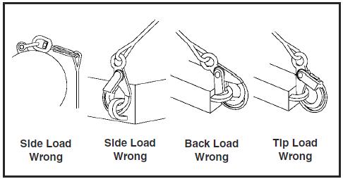
- Never side load, back load or tip load a hook. Side loading, back loading and tip loading are conditions that damage and reduce the capacity of the hook (See Figure 2).
- S-326A can be used for limited rotation (infrequent, non-continuous).
- Efficiency of synthetic sling material may be reduced when used in eye or bowl of hook.
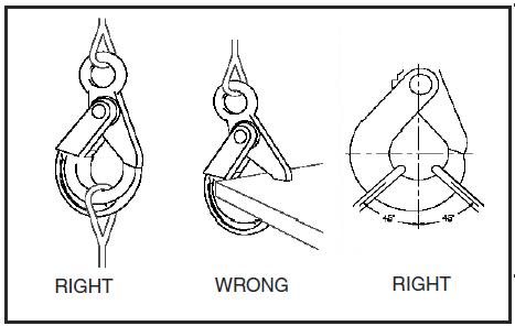
- Always make sure the hook supports the load (See Figure 3).
- Do not use hook tip for lifting (See Figure 4).
- When placing two (2) sling legs in hook, make sure the angle from vertical to the leg nearest the hook tip is not greater than 45 degrees, and the included angle between the legs does not exceed 90 degrees* (See Figure 5).
- See ANSI/ASME B30.10 "Hooks" for additional information.
- For two legged slings with angles greater than 90°, use an intermediate link such as a master link or bolt type shackle to collect the legs of the slings. The intermediate link can then be placed over the hook to provide an in-line load on the hook. This approach must also be used when using slings with three or more legs.
Important Basic Machining and Thread Information Read and Follow
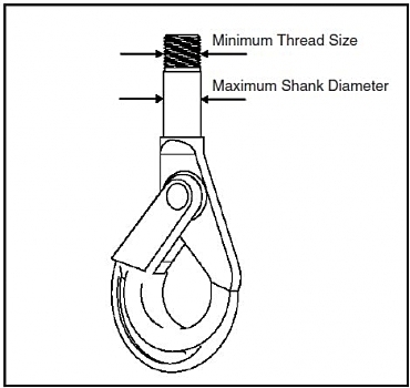
- Wrong thread and/or shank size can cause stripping and loss of load.
- The maximum diameter is the largest diameter, after cleanup, that could be expected after allowing for straight-ness, pits, etc.
- All threads must be Class 2 or better.
- The minimum thread length engaged in the nut should not be less than one (1) thread diameter.
- Hook shanks are not intended to be swaged on wire rope or rod.
- Hook shanks are not intended to be drilled (length of shank) and internally threaded.
- Crosby cannot assume responsibility for, (A) the quality of machining, (B) the type of application, or (C) the means of attachment to the power source or load.
- Consult the Crosby Hook Identification & Working Load Limit Chart (See below) for the minimum thread size for assigned Working Load Limits (WLL).f
- Remove from service any Hook which has threads corroded more than 20% of the nut engaged length.
Crosby Hook Identification & Working Load Limit Chart+
S-1316A & S-1317A Only Grade 100 Chain |
S-316A, S-317A, S-318A, S-326A |
S-318A Only |
Chain Size |
Working Load Limit
(lbs.)** 4:1 |
Grade 80 Chain |
Wire Rope XIP Mechanical Splice |
Maximum
Shank Diameter
(in.) |
Minimum Thread Size
(in.) |
(in.) |
(mm) |
Chain Size |
Working Load Limit
(lbs.)**
4:1 |
Wire Rope Size
(in.) |
Working Load Limit
(lbs.)*
5:1 |
(in.) |
(mm) |
— |
6 |
3200 |
— |
6 |
2500 |
5/16 |
2000 |
.72 |
1/2" - 13 UNC |
1/4 |
7 |
4300 |
1/4 - 5/16 |
7 - 8 |
4500 |
7/16 |
3800 |
.94 |
5/8" - 11 UNC |
5/16 |
8 |
5700 |
— |
— |
— |
— |
— |
— |
— |
3/8 |
10 |
8800 |
3/8 |
10 |
7100 |
1/2 |
5000 |
1.06 |
3/4" - 10 UNC |
1/2 |
13 |
15000 |
1/2 |
13 |
12000 |
5/8 |
7800 |
1.19 |
1" - 8 UNC |
5/8 |
16 |
22600 |
5/8 |
16 |
18100 |
7/8 |
15200 |
1.38 |
1-1/4" - 7 UNC |
3/4 |
18/20 |
35300 |
3/4 |
18/20 |
28300 |
1 |
19700 |
— |
— |
7/8 |
22 |
42700 |
7/8 |
22 |
|
— |
— |
— |
— |
1 |
26 |
59700 |
1 |
26 |
|
— |
— |
— |
— |
* Ultimate Load is 5 times the Working Load Limit based on XIP Wire Rope.
** Ultimate Load is 4 times the Working Load Limit based on Grade 80 or Grade 100 Chain.
+ Working Load Limit - The maximum mass of force which the product is authorized to support in general service when the pull is applied in-line, unless noted otherwise, with respect to the centerline of the product. This term is used interchangeably with the following terms: 1. WLL, 2. Rated Load Value, 3. SWL, 4. Safe Working Load, 5. Resultant Safe Working Load.
|