Hoist Ring HR-125/SS-125, HR-125M, SS-125M, HR-1000, HR-1000M
WARNING |
• Loads may slip or fall if proper Hoist Ring assembly and lifting procedures are not used.
• A falling load may cause serious injury or death.
• Install hoist ring bolt to torque requirements listed in tables 1, 2, 3, 4, 5 & 6 for the HR-125, HR-1000, HR125C, HR-125M, HR-1000M and HR125W, SS-125 and SS-125M respectively.
• Web sling HR-125W connecting bolt must be securely tightened in place. The jam nut must then be securely tightened onto the connecting bolt, see Table 4, last column.
• Read, understand and follow all instructions and chart information.
• Do not use with damaged slings or chain. For inspection criteria see ASME B30.9.
• Use only genuine Crosby parts as replacements.
• HR-125C chain connecting pin must be properly secured with the locking pin into the clevis ear.
• Before use tighten bolt first, then thighten nut (HR-125W). |
Hoist Ring Application Assembly Safety
Use swivel hoist ring only with a ferrous metal (steel, iron) or soft metal (i.e., aluminum) loads (work piece). Do not leave threaded end of hoist ring in aluminum loads for long time periods due to corrosion.
After determining the loads on each hoist ring, select the proper size hoist ring using the Working Load Limit ratings in Table 1, 2, 4 & 5 for UNC threads and Table 3 & 6 for Metric threads.
Drill and tap the work piece to the correct size to a minimum depth of one-half the threaded shank diameter plus the threaded shank length. See rated load limit and bolt torque requirements imprinted on top of the swivel trunnion (See Table 1 thur Table 6).
Install hoist ring to recommended torque with a torque wrench making sure the bushing flange meets the load (work piece) surface.
Never use spacers between bushing flange and mounting surface.
Always select proper load rated lifting device for use with Swivel Hoist Ring.
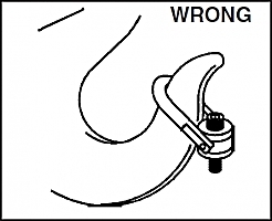
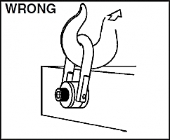
Attach lifting device ensuring free fit to hoist ring bail (lifting ring) (Fig. 1).
Apply partial load and check proper rotation and alignment. There should be no interference between load (work piece) and hoist ring bail (Fig. 2).
Special Note: When a Hoist Ring is installed with a retention nut, the nut must have a full thread engagement and must meet one of the following standards to develop the Working Load Limit (WLL).
1. ASTM A-563 (A) Grade D Hex Thick
(B) Grade DH Standard Hex
2. SAE Grade 8 — Standard Hex
Hoist Ring Inspection / Maintenance
Always inspect hoist ring before use.
Regularly inspect hoist ring parts (Fig.3).
Never use hoist ring that shows signs of corrosion, wear or damage.
Never use hoist ring if bail is bent or elongated.
Always be sure threads on shank and receiving hole are clean, not damaged, and fit properly.
Always check with torque wrench before using an already installed hoist ring.
Always make sure there are no spacers (washers) used between bushing flange and the mounting surface. Remove any spacers (washers) and retorque before use.
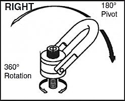
Always ensure free movement of bail. The bail should pivot 180 degrees and swivel 360 degrees (Fig. 4).
Always be sure total work piece surface is in contact with hoist ring bushing mating surface. Drilled and tapped hole must be 90 degrees to load (work piece) surface.
Operating Safety
Never exceed the capacity of the swivel hoist ring, see Tables 1, 2, 4 and 5 for UNC threads and Tables 3 and 6 for Metric threads. (see next page for tables)
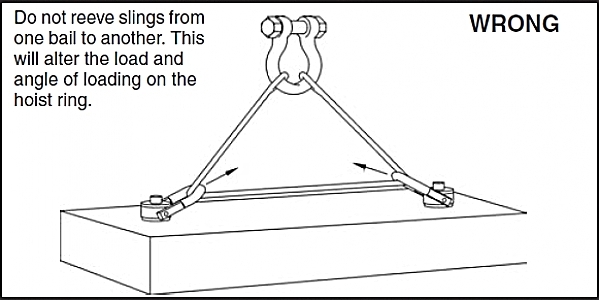
When using lifting slings of two or more legs, make sure the forces in the legs are calculated using the angle from the horizontal sling angle to the leg and select the proper size swivel hoist ring to allow for the angular forces.
|
|
Figure 1 |
Figure 2 |
|
|
Figure 3 |
Figure 4 |
Table 1
Working Load Limit* 5:1 (lbs.) |
Hoist Ring Bolt Torque in
Ft. lbs. t |
HR-125 |
HR-1000 |
Bolt Size t
(in.) |
Effective Thread
Projection Length (in.) |
Bolt Size t
(in.) |
Effective Thread
Projection Length
(in.) |
800 ft |
7 |
5/16 - 18 x 1.50 |
.59 |
5/16 - 18 x 1.50 |
.52 |
1000 ft |
12 |
3/8 - 16 x 1.50 |
.59 |
3/8 - 16 x 1.50 |
.52 |
2500 |
28 |
1/2 - 13 x 2.00 |
.71 |
1/2 - 13 x 2.25 |
.69 |
2500 ft |
28 |
1/2 - 13 x 2.50 |
1.21 |
1/2 - 13 x 2.75 |
1.19 |
4000 |
60 |
5/8 - 11 x 2.00 |
.71 |
5/8 - 11 x 2.25 |
.69 |
4000 ft |
60 |
5/8 - 11 x 2.75 |
1.46 |
5/8 - 11 x 3.00 |
1.44 |
5000 |
100 |
3/4 - 10 x 2.25 |
.96 |
3/4 - 10 x 2.50 |
.94 |
5000 tt |
100 |
3/4 - 10 x 2.75 |
1.46 |
3/4 - 10 x 3.00 |
1.44 |
7000 ** |
100 |
3/4 - 10 x 2.75 |
.90 |
3/4 - 10 x 3.00 |
.85 |
7000 ft** |
100 |
3/4 - 10 x 3.50 |
1.65 |
3/4 - 10 x 3.50 |
1.35 |
8000 |
160 |
7/8 - 9 x 2.75 |
.90 |
7/8 - 9 x 3.00 |
.85 |
8000 tt |
160 |
7/8 - 9 x 3.50 |
1.65 |
7/8 - 9 x 3.50 |
1.35 |
10000 |
230 |
1 - 8 x 3.00 |
1.15 |
1 - 8 x 3.50 |
1.35 |
10000 tt |
230 |
1 - 8 x 4.00 |
2.15 |
1 - 8 x 4.50 |
2.35 |
15000 |
470 |
1-1/4 - 7 x 4.50 |
2.22 |
1-1/4 - 7 x 5.00 |
2.09 |
24000 |
800 |
1-1/2 - 6 x 6.50 |
2.98 |
1-1/2 - 6 x 5.50 |
2.59 |
30000 |
1100 |
2 - 4-1/2 x 6.50 |
2.98 |
— |
— |
50000 |
2100 |
2-1/2 - 4 x 8.00 |
4.00 |
— |
— |
75000 |
4300 |
3 - 4 x 10.50 |
5.00 |
— |
— |
100000 |
5100 |
3-1/2 - 4 x 13.00 |
7.00 |
— |
— |
** Ultimate Load is 4.5 times Working Load Limit for 7000# Hoist Ring when Tested in 90° orientation. All sizes are individually proof tested to 2-1/2 times the Working Load Limit. *, t, tt, t (See footnote at bottom of page).
Table 2 |
HR-125C Swivel Hoist Ring to Grade 8 Chain |
Working Load Limit 4:1
(lbs.) ** |
Hoist Ring Bolt Torque in Ft. lbs. t |
Bolt Size (in.) tt |
Effective Thread
Projection Length
(in.) |
Spectrum 8 Chain Size (in. - mm) |
4500 |
60 |
5/8 - 11 x 2.00 |
.71 |
1/4 - 5/16 - 7 - 8 |
4500 tt |
60 |
5/8 - 11 x 2.75 |
1.46 |
1/4 - 5/16 - 7 - 8 |
7100 |
100 |
3/4 - 10 x 2.75 |
.90 |
3/8 - 10 |
7100 tt |
100 |
3/4 - 10 x 3.50 |
1.65 |
3/8 - 10 |
12000 |
230 |
1 - 8 x 3.00 |
1.15 |
1/2 - 13 |
12000 tt |
230 |
1 - 8 x 4.00 |
2.15 |
1/2 - 13 |
18100 |
470 |
1-1/4 - 7 x 4.50 |
2.22 |
5/8 - 16 |
Table 3 |
Working Load Limit (KG) *** |
Hoist Ring Bolt Torque in Nm t |
HR-125M |
HR-1000M |
Design Factor 5:1 |
Design Factor 4:1 |
Bolt Size łł (mm) |
HR-125M
Effective Thread Projection Length (mm) |
Bolt Sizełł (mm) |
Effictive Thread Projection Length (mm) |
400 |
500 |
10 |
M 8 X 1.25 X 40 |
16.9 |
M 8 X 1.25 X 40 |
15.2 |
450 |
550 |
16 |
M 10 X 1.50 X 40 |
16.9 |
M 10 X 1.50 X 40 |
15.2 |
1050 |
1300 |
38 |
M 12 X 1.75 X 50 |
17.2 |
M 12 X 1.75 X 55 |
15.2 |
1900 |
2400 |
81 |
M 16 X 2.00 X 60 |
27.2 |
M 16 X 2.00 X 65 |
25.5 |
2150 |
2700 |
136 |
M 20 X 2.50 X 65 |
31.2 |
M 20 X 2.50 X 70 |
30.5 |
3000 |
3750 |
136 |
M 20 X 2.50 X 75 |
28.1 |
M 20 X 2.50 X 80 |
25.4 |
4200 |
5250 |
312 |
M 24 X 3.00 X 80 |
33.1 |
M 24 X 3.00 X 90 |
35.4 |
7000 |
8750 |
637 |
M 30 X 3.50 X 120 |
65.1 |
M 30 X 3.50 X 140 |
66.2 |
11000 |
13750 |
1005 |
M 36 X 4.00 X 150 |
60.6 |
M 36 X 4.00 X 130 |
56.2 |
12500 |
15600 |
1005 |
M 42 X 4.50 X 160 |
70.6 |
— |
— |
13500 |
16900 |
1350 |
M 48 X 5.00 X 160 |
101 |
— |
— |
* Ultimate load is 5 times the Working Load Limit. Individually proof tested to 2-1/2 times the Working Load Limit. ** Ultimate load is 4 times the Working Load Limit. Individually proof tested to 2-1/2 times the Working Load Limit. *** Individually proof tested to 2-1/2 times the Working Load Limit based on 4:1 design factor. t Tightening torque values shown are based upon threads being clean, dry and free of lubrication.
tt Long bolts are designed to be used with soft metal (i.e., aluminum) work piece. While the long bolts may also be used with ferrous metal
(i.e., steel & iron) work pieces, short bolts are designed for ferrous work pieces only.
t Bolt specification is a Grade 8 Alloy socket head cap screw to ASTM A574. All threads are UNC.
tt Bolt specification is a Grade 12.9 Alloy socket head cap screw to DIN 912. All threads are metric (ASME/ANSI B18.3.1m) All Swivel Hoist Rings are individually proof tested.
Table 4 |
HR-125W Swivel Hoist Ring to Webbing |
HR-125W Web Sling |
HR-125W Working Load Limit 5:1 (tons) * |
Hoist Ring Bolt Torque in Ft. lbs. + |
Bolt Size (in.) ++ |
Effective Thread Projection Lenght (in.) |
Torque in Ft. - lbs. Spool bolt and nut ++++ |
Round Sling Size (in.) |
Web Width (in.) |
Eye Width (in.) |
Ply. |
1 & 2 |
2 |
2 |
2 |
3-1/4 |
100 |
3/4 - 10 x 2.75 |
.90 |
90 |
1 & 2 |
2 |
2 |
2 |
3-1/4 |
100 |
3/4 - 10 x 3.50 |
1.65 |
90 |
3 |
3 |
1.5 |
2 |
4-1/2 |
230 |
1 - 8 x 3.00 |
1.15 |
110 |
3 |
3 |
1.5 |
2 |
4-1/2 |
230 |
1 - 8 x 4.00 |
2.15 |
110 |
4 |
4 |
2 |
2 |
6-1/4 |
470 |
1-1/4 - 7 x 4.50 |
2.22 |
130 |
|
Table 5 |
SS-125 ¥¥ |
Working Load Limit (lbs.) ¥ |
Torque in
Ft. Lbs. t |
Bolt Size (in.) § |
Effective Thread Projection
(in.) |
400 |
3.5 |
5/16 - 18 x 1 |
.29 |
400 |
3.5 |
5/16 - 18 x 1.25 |
.54 |
500 |
6 |
3/8 - 16 x 1.25 |
.54 |
1250 |
14 |
1/2 - 13 x 2 |
.78 |
1250 |
14 |
1/2 - 13 x 2.25 |
1.03 |
1250 |
14 |
1/2 - 13 x 2.5 |
1.28 |
2000 |
30 |
5/8 - 11 x 2 |
.78 |
2000 |
30 |
5/8 - 11 x 2.25 |
1.03 |
2000 |
30 |
5/8 - 11 x 2.5 |
1.28 |
2500 |
50 |
3/4 - 10 x 2.25 |
1.03 |
2500 |
50 |
3/4 - 10 x 2.75 |
1.53 |
3500 |
50 |
3/4 - 10 x 2.75 |
1.04 |
3500 |
50 |
3/4 - 10 x 3.25 |
1.54 |
4000 |
80 |
7/8 - 9 x 2.75 |
1.04 |
4000 |
80 |
7/8 - 9 x 3 |
1.29 |
5000 |
115 |
1 - 8 x 3 |
1.29 |
5000 |
115 |
1 - 8 x 3.25 |
1.54 |
5000 |
115 |
1 - 8 x 4 |
2.29 |
7500 |
235 |
1-1/4 - 7 x 4 |
1.89 |
12000 |
400 |
1-1/2 - 6 x 5.5 |
2.70 |
15000 |
400 |
2 - 4-1/2 x 5.75 |
2.96 |
25000 |
1050 |
2-1/2 - 4 x 8 |
4.00 |
25000 |
1050 |
2-1/2 - 8 x 8 |
4.00 |
37500 |
2150 |
3 - 4 x 10.25 |
5.00 |
50000 |
2550 |
3-1/2 - 4 x 13 |
7.00 |
|
Table 6 |
SS-125M ¥¥ |
Working Load Limit (Kg) ¥ |
Torque
in Nm t |
Bolt Size (mm) §§ |
Effective Thread Projection (mm) |
200 |
4 |
M 8 x 1.25 |
13 |
250 |
8 |
M 10 x 1.50 |
18 |
525 |
18 |
M 12 x 1.75 |
19 |
950 |
40 |
M 16 x 2.00 |
29 |
1075 |
68 |
M 20 x 2.50 |
34 |
1500 |
68 |
M 20 x 2.50 |
32 |
2100 |
108 |
M 24 x 3.00 |
37 |
2100 |
108 |
M 30 x 3.50 |
58 |
3500 |
318 |
M 30 x 3.50 |
42 |
3500 |
318 |
M 30 x 3.50 |
62 |
5500 |
542 |
M 36 x 4.00 |
64 |
6250 |
542 |
M 42 x 4.50 |
82 |
6750 |
542 |
M 48 x 5.00 |
82 |
11150 |
1423 |
M 64 x 6.00 |
101 |
15750 |
2915 |
M 72 x 6.00 |
132 |
22300 |
3459 |
M 90 x 6.00 |
177 |
* Ultimate load is 5 times the Working Load Limit. Individually proof tested to 2-1/2 times the Working Load Limit.
t Tightening torque values shown are based upon threads being clean, dry and free of lubrication.
t Bolt specification is a Grade 8 Alloy socket head cap screw to ASTM A574. All threads are UNC .
ttt Tighten bolt to specified torque, then tighten nut to specified torque. ¥ Ultimate load is 5 times the Working Load Limit. Individually proof tested to 2 times the Working Load Limit.
¥¥ All components are 316 Stainless Steel, except Bolt Retainers, which are made from15-7 PH (UNS 15700) magnetic stainless steel. § Bolt specification is 316 Stainless Steel socket head cap screw to ASTM F837 Group 1 (316).
§§ Bolt specification is 316 Stainless Steel socket head cap screw to ASTM F837M (316). All threads are Metric (ASME/ANSI B18.3.1M). |
|
| |
|
| |
|
| |
|
|