Hoist Ring HR-1200
HR-1200
WARNING |
- Loads may slip or fall if proper Hoist Ring assembly and lifting procedures are not followed.
- A falling load may cause serious injury or death.
- Install hoist ring bolt to torque requirements listed in tables.
- The side pull hoist ring frame will be only one part of a lifting system with several components (i.e., shackles and slings). Never exceed the Working Load Limit of the hoist ring frame.
- Do not use damaged slings or chain. For inspection criteria, see ASME B30.9.
- Read and understand these instructions before using hoist ring.
- Use only genuine Crosby parts as replacements.
|
Hoist Ring Application / Assembly Instruction
- The Crosby side pull swivel hoist ring is designed to accept standard Crosby fittings to facilitate wider slings and quick attachment. In order to use the larger fittings, the load rating on the (shackle) fitting may be greater than the hoist ring frame. Never exceed the Working Load Limit of the hoist ring frame.
- Use swivel hoist ring only with a ferrous metal (steel, iron) or non-ferrous (i.e., aluminum) loads (work piece). Do not leave threaded end of hoist ring in aluminum loads for long time periods due to corrosion.
- After determining the loads on each hoist ring, select the proper size hoist ring using the Working Load Limit ratings in Table 1 for UNC threads and Table 2 for Metric threads.
- Drill and tap the work piece to the correct size to a minimum depth of one-half the threaded shank diameter plus the threaded shank length.
- Install hoist ring to recommended torque with a torque wrench making sure the bushing flange is fully supported by the load (work piece) surface. See rated load limit and bolt torque requirements imprinted on hoist ring body (See Table 1 or Table 2).
- Never use spacers between bushing flange and mounting surface.
- Always select proper lifting device for use with Swivel Hoist Ring (See Tables 1 & 2).
- Attach lifting device ensuring free fit to hoist shackle (See Figure 3).
- Apply partial load and check proper rotation and alignment of shackle. There should be no interference between load (work piece) and hoist shackle (See Figure 1 and Figure 3).
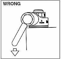
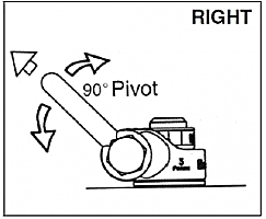
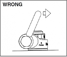
- The Hoist ring should rotate into normal operating position, with shackle aligned with load as shown in Figure 3. If shackle is oriented as shown in Figure 4, DO NOT LIFT.
- Special Note: when a Hoist Ring is installed with a retention nut, the nut must have full thread engagement and must meet one of the following standards to develop the Working Load Limit (WLL).
- ASTM A-563 (A) Grade D Hex Thick (B) Grade DH Standard Hex
- SAE Grade 8 - Standard Hex
|
|
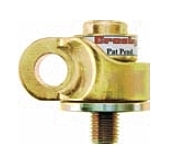
Figure 1 |
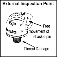
Figure 2
|
|
|
Figure 3 |
Figure 4 |
Hoist Ring Inspection / Maintenance
- Always inspect hoist ring before use.
- Regularly inspect hoist ring parts (Figure 2).
- For hoist rings used in frequent load cycles or on pulsating loads, the bolt threads should be periodically inspected by magnetic particle or dye penetrant.
- Do not use part showing cracks, nicks or gouges.
- Repair minor nicks or gouges to hoist frame by lightly grinding until surfaces are smooth. Do not reduce original dimension more than 10%. Do not repair by welding
- Never use hoist ring that shows signs of corrosion, wear or damage.
- Never use hoist ring if components are bent or elongated.
- Always be sure threads on bolt and receiving tapped holes are clean, undamaged, and fit properly.
- Always check with torque wrench before using an already installed hoist ring.
- Always make sure there are no spacers (washers) used between bushing flange and the mounting surface. Remove any spacers (washers) and retorque before use.
- Always ensure free movement of shackle. The shackle should pivot 90° and the hoist ring should swivel 360° (See Figure 3).
- Always be sure total work piece surface is in contact with hoist ring bushing mating surface. Drilled and tapped hole must be 90° to load (work piece) surface.
OPERATING SAFETY
- Never exceed the capacity of the hoist ring, see Table 1 for UNC threads and Table 2 for Metric threads.
- When using lifting slings of two or more legs, make sure the forces in the legs are calculated using the angle from the horizontal sling angle to the leg and select the proper size swivel hoist ring to allow for the angular forces.
HR1200 UNC Threads TABLE 1
Frame
Size |
Working
Load
Limit *
(lbs.) |
Hoist
Ring
Bolt
Torque
in Ft.
Lbs. + |
Bolt Size +++ (in.)
|
Effective
Thread
Projection
Length
(in.) |
Recommended Shackles |
Red Pin ® Shackles
209, 210, 213 215,
2130, 2150
(tons) |
Red Pin ® Web
Shackles S-281
(tons) |
1 |
650++
800++ |
7
12
|
5/16-18x1.5
3/8-18x1.5
|
.59
.59 |
1/2" - (2)
5/8" - (3-1/4) |
2"- (3-1/4) |
2 |
2000 2000++
3000
3000++ |
28
28
60
60 |
1/2 - 13 x 2.0
1/2 - 13 x 2.5
5/8 - 11 x 2.0
5/8 - 11 x 2.75 |
.71
1.21
.71
1.46 |
5/8" - (3-1/4)
3/4" - (4-3/4) |
2" - (3-1/4)
1-1/2" - (4-1/2) |
3 |
5000 5000++
6500
6500++
8000
8000++ |
100
100
160
160
230
230 |
3/4 - 10 x 2.75
3/4 - 10 x 3.5
7/8 - 9 x 2.5
7/8 - 9 x 3.5
1 - 8 x 3.0
1 - 8 x 4.0 |
1.46
1.63
.90
1.65
1.15
2.15 |
7/8" - (6-1/2) |
2" - (6-1/4) |
4 |
14000 |
470 |
1-1/4 - 7 x 4.5 |
2.22 |
1" - (8-1/2)
1-1/8" - (9-1/2)
1-1/4" - (12) |
3" - (8-1/2) |
5 |
17200 29000 |
800
1100 |
1-1/2 - 6 x 6.5
2 - 4-1/2 x 6.5 |
2.98
2.98 |
1-3/8" - (13-1/2)
1-1/2" - (17)
1-3/4" - (25) |
— |
HR1200M Metric Threads TABLE 2
Frame
Size |
Working
Load
Limit *
(kg) |
Hoist
Ring
Bolt
Torque
Nm + |
Bolt Size (mm) ++++
|
Effective
Thread
Projection
Length
(mm) |
Recommended Shackles |
Red Pin ®
Shackles 209, 210, 213 215, 2130, 2150
(tons) |
Red Pin ®
Web Shackles
S-281 (tons) |
1 |
300
400 |
10
16 |
M8 x 1.25 x 40
M10 x 1.5 x 40 |
16.9
16.9 |
1/2" - (2)
5/8" - (3-1/4) |
2" - (3-1/4) |
2 |
1000 1400 |
38
81 |
M12 x 1.75 x 50
M16 x 2.00 x 60 |
17.2
27.2 |
5/8" - (3-1/4)
3/4" - (4-3/4) |
2" - (3-1/4)
1-1/2" - (4-1/2) |
3 |
2250
3500 |
136
312 |
M20 x 2.50 x 75
M24 x3.00 x 80 |
28.1
33.1 |
7/8" - (6-1/2) |
2" - (6-1/4) |
4 |
6250 |
637 |
M30 x 3.5 x 120 |
45.1 |
1" - (8-1/2)
1-1/8" - (9-1/2)
1-1/4" - (12) |
3" - (8-1/2) |
5 |
7750
10000
13000 |
1005 1005 1350 |
M36 x 4.0 x 150
M42 x 4.5 x 160
M48 x 5.0 x 160 |
60.6
70.6
70.6 |
1-3/8" - (13-1/2)
1-1/2" - (17)
1-3/4" - (25) |
— |
Designed to be used with Ferrous work piece only
* Ultimate load is 5 times the Working Load Limit. Individually proof tested to 2-1/2 times the Working Load Limit.
+ Tightening torque values shown are based upon threads being clean, dry and free of lubrication.
++ Long bolts are designed to be used with soft metal (i.e., aluminum) work piece. While the long bolts may also be used with ferrous metal (i.e., steel & iron) work pieces, short bolts are designed for ferrous work pieces only.
+++Bolt specification is a Grade 8 Alloy socket head cap screw to ASTM A574. All threads are UNC - 3A.
++++Bolt specification is a Grade 12.9 Alloy socket head cap to DIN 912. All threads are metric (ASME/ANSI B18.3.1m).
|