Hoist Hooks
 |
WARNING |
- Loads may disengage from hook if proper procedures are not followed.
- A falling load may cause serious injury or death.
- See OSHA Rule 1926.550(g) for personnel hoisting by cranes and derricks, and OSHA Directive CPL 2-1.29 - Interim Inspection Procedures During Communication Tower Construction Activities. A Crosby 319, 320 or 322 hook with a PL latch attached and secured with a bolt, nut and cotter pin (or toggle pin) may be used for lifting personnel.
- A Crosby 319N, 320N or 322N hook with an S-4320 latch attached and secured with cotter pin or bolt, nut and pin; or a PL-N latch attached and secured with toggle pin may be used for lifting personnel. A hook with a Crosby SS-4055 latch attached shall NOT be used for personnel lifting.
- See OSHA Directive CPL 2-1.29 - Crosby does not recommend the placement of lanyards directly into the positive locking Crosby hook when hoisting personnel. Crosby requires that all suspension systems (vertical lifelines / lanyard) shall be gathered at the positive locked load hook by use of a master link, or a bolt-type shackle secured with cotter pin.
- Threads may corrode and/or strip and drop the load.
- Remove securement nut to inspect or to replace S-322, S-3316 and S-3319 bearing washers (2).
- Hook must always support the load. The load must never be supported by the latch.
- Never apply more force than the hook's assigned Working Load Limit (WLL) rating.
- Read and understand these instructions before using hook.
|
 |
QUIC-CHECK® Hoist hooks incorporate markings forged into the product which address two (2) QUIC-CHECK® features: Deformation Indicators - Two strategically placed marks, one just below the shank or eye and the other on the hook tip, which allows for a QUIC-CHECK® measurement to determine if the throat opening has changed, thus indicating abuse or overload.
To check, use a measuring device (i.e., tape measure) to measure the distance between the marks. The marks should align to either an inch or half-inch increment on the measuring device. If the measurement does not meet criteria, the hook should be inspected further for possible damage.
Angle Indicators - Indicates the maximum included angle which is allowed between two (2) sling legs in the hook. These indicators also provide the opportunity to approximate other included angles between two sling legs.
IMPORTANT SAFETY INFORMATION -READ AND FOLLOW
- A visual periodic inspection for cracks, nicks, wear, gouges and deformation as part of a comprehensive documented inspection program, should be conducted by trained personnel in compliance with the schedule in ANSI B30.10.
- For hooks used in frequent load cycles or pulsating loads, the hook and threads should be periodically inspected by Magnetic
- Particle or Dye Penetrant. (Note: Some disassembly may be required.)
- Never use a hook whose throat opening has been increased, or whose tip has been bent more than 10 degrees out of plane from the hook body, or is in any other way distorted or bent. Note: A latch will not work properly on a hook with a bent or worn tip.
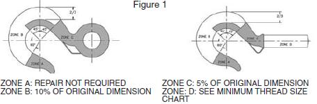
- Never use a hook that is worn beyond the limits shown in Figure 1.
- Remove from service any hook with a crack, nick, or gouge. Hooks with a nick or gouge shall be repaired by grinding lengthwise, following the contour of the hook, provided that the reduced dimension is within the limits shown in Figure 1. Contact Crosby Engineering to evaluate any crack.
- Never repair, alter, rework, or reshape a hook by welding, heating, burning, or bending.
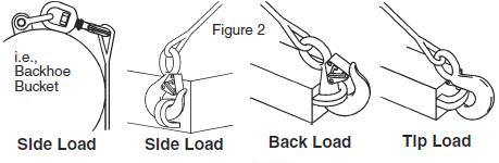
- Never side load, back load, or tip load a hook.(Side loading, back loading and tip loading are conditions that damage and reduce the capacity of the hook). (See Figure 2).
- Eye hooks, shank hooks and swivel hooks are designed to be used with wire rope or chain. Efficiency of assembly may be reduced when used with synthetic material.
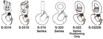
- Do not swivel the S-322, S-3316, or S-3319 swivel hooks while supporting a load. These hooks are distinguishable by hex nuts and flat washers.
- The S-3322 swivel hook is designed to rotate under load. The S-3322 is distinguishable from the S-322 by use of a round nut designed to shield bearing.
- The frequency of bearing lubrication on the S-3322 depends upon frequency and period of product use as well as environmental conditions, which are contingent upon the user's good judgement.
- The use of a latch may be mandatory by regulations or safety codes; e.g., OSHA, MSHA, ANSI/ASME B30, Insurance, etc.. (Note: When using latches, see instructions in "Understanding: The Crosby Group Warnings" for further information.)
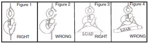
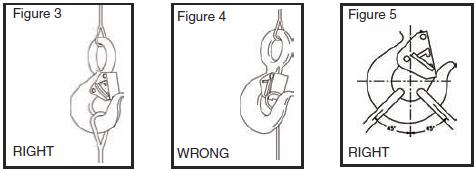
- Always make sure the hook supports the load. (See Figure 3). The latch must never support the load (See Figure 4).
- When placing two (2) sling legs in hook, make sure the angle from the vertical to the outermost leg is not greater than 45 degrees, and the included angle between the legs does not exceed 90 degrees* (See Figure 5).
- See ANSI/ASME B30.10 "Hooks" for additional information.
 |
 |
 |
READ AND UNDERSTAND THESE INSTRUCTIONS BEFORE USING HOOKS IMPORTANT - BASIC MACHINING AND THREAD INFORMATION
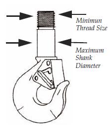 |
- Wrong thread and/or shank size can cause stripping and loss of load.
- The maximum diameter is the largest diameter, after cleanup, that could be expected after allowing for straightness, pits, etc.
- All threads must be Class 2 or better.
- The minimum thread length engaged in the nut should not be less than one (1) thread diameter. Install a properly sized retention device to secure the nut to the hook shank after the nut is properly adjusted at assembly. Nut retention devices such as set screws or roll pins are suitable for applications using anti-friction thrust bearings or bronze thrust washers. If the hook is intended for other applications that introduce a higher torque into the nut, a more substantial retaining device may be required.
- Hook shanks are not intended to be swaged on wire rope or rod. See S319SWG for hook designed for swaging.
- Hook shanks are not intended to be drilled (length of shank) and
- Crosby can not assume responsibility for, (A) the quality of machining, (B) the type of application, or (C) the means of attachment to the power source or load.
- Consult the Crosby Hook Identification & Working Load Limit Chart (See below) for the minimum thread size for assigned Working Load Limits (WLL).t
- Remove from service any Hook which has threads corroded more than 20% of the nut engaged length.
CROSBY HOOK IDENTIFICATION & WORKING LOAD LIMIT CHART+
Hook Identification |
Working Load Limit |
Maximum Shank Dimeter after Machining
(in.)
|
Minimum Thread Size |
319-C,
319-CN
320-C,
320-CN
322-C,
322-CN |
319 A,
319-AN
320-A,
320-AN
322-A,
322-AN
3319,
3322B |
319-BN |
319-C,
319-CN
320-C,
320-CN
322-C,
322-CN |
319-A,
319-AN
320-A,
320-AN
322-A,
322-AN
S-3322B |
319-BN |
S-3319 |
319-BN |
319-A
319-AN
(Alloy)
319-BN
(Bronze) |
DC |
DA |
DB |
.75 |
1 |
.5 |
- |
.53 |
1/2 - 13unc |
1/2 - 13 unc |
FC |
FA |
FB |
1 |
1.5 |
.6 |
- |
.62 |
5/8 - 11unc |
5/8 - 11 unc |
GC |
GA |
GB |
1.5 |
2 |
1 |
- |
.66 |
5/8 - 11unc |
5/8 - 11 unc |
HC |
HA |
HB |
2 |
3 |
1.4 |
1.63 |
.81 |
3/4 - 10unc |
3/4 - 10 unc |
IC |
IA |
IB |
3 |
*4.5 / 5 |
2.0 |
2.5 |
1.03 |
7/8 - 9unc |
7/8 - 9 unc |
JC |
JA |
JB |
5 |
7 |
3.5 |
4.5 |
1.27 |
1-1/8 - 7unc |
1-1/8 - 7 unc |
KC |
KA |
KB |
7.5 |
11 |
5.0 |
- |
1.52 |
1-1/4 - 7unc |
1-3/8 - 6 unc |
LC |
LA |
LB |
10 |
15 |
6.5 |
- |
1.75 |
1-5/8 - 8un |
1-5/8 - 8 un |
NC |
NA |
NB |
15 |
22 |
10 |
- |
2.00 |
2 - 8un |
2 - 8 un |
OC |
OA |
— |
20 |
30 |
- |
- |
2.50 |
2-1/4 - 8un |
2-1/4 - 8 un |
PC |
PA |
— |
25 |
37 |
- |
- |
3.50 |
2-3/4 - 8un |
2-3/4 - 8 un |
SC |
SA |
— |
30 |
45 |
- |
- |
3.50 |
3 - 8un |
3 - 8 un |
TC |
TA |
— |
40 |
60 |
- |
- |
4.00 |
3-1/4 - 8un |
3-1/2 - 8 un |
UC |
UA |
— |
50 |
75 |
- |
- |
4.50 |
3-3/4 - 8un |
4 - 4 unc |
— |
WA |
— |
— |
100 |
- |
- |
6.12 |
— |
4-1/2 - 8 un |
— |
XA |
— |
— |
150 |
- |
- |
6.36 |
— |
5-1/2 - 8 un |
— |
YA |
— |
— |
200 |
- |
- |
7.00 |
— |
6-1/4 - 8 un |
— |
ZA |
— |
— |
300 |
- |
- |
8.62 |
— |
7-1/2 - 8 un |
• 319AN, 320-AN, 3322 and 322AN are rated at 5 tons.
+ Working Load Limit - The maximum mass or force which the product is authorized to support in general service when the pull is applied in-line, unless noted noted otherwise, with respect to the centerline of the product. This term is used interchangeably with the following terms: 1. WLL, 2. Rated Load Value, 3. SWL, 4. Safe Working Load, 5. Resultant Safe Working Load.
Warning and Application Instructions For CROSBY® HOOK LATCH KIT
WARNING |
- Loads may disengage from hook if proper procedures are not followed.
- A falling load may cause serious injury or death.
- See OSHA Rule 1926.550 (g)(4)(iv)(B) for personnel hoisting for cranes and derricks. Only a Crosby or McKissick hook with a PL Latch attached and secured with bolt, nut and cotter (or Crosby Toggle Pin) or a Crosby hook with a S-4320 Latch attached and secured with a cotter pin, or a Crosby SHUR-LOC® hook in the locked position may be used for any personnel hoisting. A hook with a Crosby SS-4055 latch attached shall NOT be used for personnel lifting.
- Hook must always support the load. The load must never be supported by the latch.
- Read and understand these instructions before using hook and latch.
- Important Safety Information - Read & Follow
|
- Always inspect hook and latch before using.
- Never use a latch that is distorted or bent.
- Always make sure spring will force the latch against the tip of the hook.
- Always make sure hook supports the load. The latch must never support the load. (See Figure 1 & 2).
- When placing two (2) sling legs in hooks, make sure the angle between the legs is less the 90° and if the hook or load is tilted, nothing bears against the bottom of this latch. (See Figures 3 & 4).
- Latches are intended to retain loose sling or devices under slack conditions.
- Latches are not intended to be an anti-fouling device.
|